Friday 2 March 2018

How to Make a Line Following Robot without Microcontroller

Line Following Robot 


Learn - how to make a Line follower robot Without microcontroller DIY at home


It is a Robert that follows a line, either a black line on white surface. 

IR sensor will send a HIGH digital signal ("1"). similarly when the sensor is on a black surface IR rays will be emitted and will not be reflected back which will be absorbed by the black surface, in this state the IR sensor will send LOW digital signal ("0"). Thus with these digital values 1 and 0 we can easily identify the state of the sensors

Required Components :- 

1. Zero PCB Board 
2. IR Infrared Obstacle Avoidance Sensor Module 
3. 16 pin Ic base 
4. L293d ic base 
5. 60W Multi Purpose Hot Melt Glue Gun 
6. 7805 voltage regulator 
7. wood bit (10cm x 5cm x 2.5cm) 
8. BO Motor L Type - 60 RPM 
9. Red BO Motor Wheels 
10. plexiglass piece (10 x 5 cm) 
11. soldering wire 50gm 
12. Yellow Soldering Iron 
13. 10K ohm Variable Resistor 
14. Resistor(100ohm, 1k, 10K) etc.

Diagram:


INPUT 1,2,3 and 4 of L293D will be thrown back to the OUTPUT 1,2,3 and 4 respectively. The INPUT 2 and 3 of L293D is connected to ground which is LOW("0") and the signal from the IR sensors are connected to INPUT 1 and 4. Hence the value of OUTPUT 2 and 3 will be constantly LOW("0") while the value of OUTPUT 1 and 4 will be HIGH("1") when the IR sensor is on the white surface and will be LOW("0") when the sensor is on black surface

Line Follower Robot using Arduino

IR sensor modules namely left sensor and right sensor. When both left and right sensor senses white then robot move forward


source code:


/*------ Arduino Line Follower Code----- */
/*-------definning Inputs------*/
#define LS 2      // left sensor
#define RS 3      // right sensor
/*-------definning Outputs------*/
#define LM1 4       // left motor
#define LM2 5       // left motor
#define RM1 6       // right motor
#define RM2 7       // right motor
void setup()
{
  pinMode(LS, INPUT);
  pinMode(RS, INPUT);
  pinMode(LM1, OUTPUT);
  pinMode(LM2, OUTPUT);
  pinMode(RM1, OUTPUT);
  pinMode(RM2, OUTPUT);
}

void loop()
{
  if(digitalRead(LS) && digitalRead(RS))     // Move Forward
  {
    digitalWrite(LM1, HIGH);
    digitalWrite(LM2, LOW);
    digitalWrite(RM1, HIGH);
    digitalWrite(RM2, LOW);
  }

  if(!(digitalRead(LS)) && digitalRead(RS))     // Turn right
  {
    digitalWrite(LM1, LOW);
    digitalWrite(LM2, LOW);
    digitalWrite(RM1, HIGH);
    digitalWrite(RM2, LOW);
  }

  if(digitalRead(LS) && !(digitalRead(RS)))     // turn left
  {
    digitalWrite(LM1, HIGH);
    digitalWrite(LM2, LOW);
    digitalWrite(RM1, LOW);
    digitalWrite(RM2, LOW);
  }

  if(!(digitalRead(LS)) && !(digitalRead(RS)))     // stop
  {
    digitalWrite(LM1, LOW);
    digitalWrite(LM2, LOW);
    digitalWrite(RM1, LOW);
    digitalWrite(RM2, LOW);
  }
}

............................................................................................................................................................

.


More projects:


How to How to Make a Self Balancing Robot

How to Make a Self Balancing Robot


Learn- How to make a self balancing robot by using Arduino.In this project i'm gonna show you the easiest way to do a simple, cheap and useless two wheels self-balancing robotI explain the materials and electronics used in the project, how and where to buy or create it and i'm gonna tell you my experience and tips.


Required of Components 


  1. Arduino Mega
  2. b6612Fng Dual Motor Driver
  3. Bluetooth Module BLE 4.0 MPU 6050
  4. Lipo Battery
  5. Motor and Wheels
  6. WHOLE KIT

Diagram:


The electronics we are going to use in the project are simply three, an arduino UNO you can use whatever arduino you have, doesn't matter if isn't arduino UNO a motor driver, in this case a L298, and finally an IMU.


Next Step


Source Code:

how To download and Use Arduino Uno Software under Windows


Self Balancing Robot Source Code  Download Link click here


Mouse Controlled Arduino LEDS blinking

Mouse Controlling Arduino LEDs


Use a mouse to control LEDs Connected to an Arduino.pelase following the steps


Required of Components 

Arduino UNO
  1. Breadboard
  2. 9 LEDs
  3. 9 x 330 ohm resistors
  4. Wires to connect the circuit
  5. USB connection cable: to connect the computer to the Arduino
  6. A computer: to run the processing sketch, and to compile / upload the Arduino sketch
  7. Processing Program installed on computer
  8. Arduino Program installed on the computer

Diagram


Sourcre Code

1
 2
 3
 4
 5
 6
 7
 8
 9
10
11
12
13
14
15
16
17
18
19
20
21
22
23
24
25
26
27
28
29
30
31
32
33
34
35
36
37
38
39
40
41
42
/* This program was created by ScottC on 9/5/2012 to receive serial 
signals from a computer to turn on/off  1-9 LEDs */

void setup() {                
  // initialize the digital pins as an output.
  pinMode(2, OUTPUT);
  pinMode(3, OUTPUT);
  pinMode(4, OUTPUT);
  pinMode(5, OUTPUT);
  pinMode(6, OUTPUT);
  pinMode(7, OUTPUT);
  pinMode(8, OUTPUT);
  pinMode(9, OUTPUT);
  pinMode(10, OUTPUT);
// Turn the Serial Protocol ON
  Serial.begin(9600);
}

void loop() {
  byte byteRead;

   /*  check if data has been sent from the computer: */
  if (Serial.available()) {
  
    /* read the most recent byte */
    byteRead = Serial.read();
    //You have to subtract '0' from the read Byte to convert from text to a number.
    byteRead=byteRead-'0';
    
    //Turn off all LEDS
    for(int i=2; i<11; i++){
      digitalWrite(i, LOW);
    }
    
    if(byteRead>0){
      //Turn on the relevant LEDs
      for(int i=1; i<(byteRead+1); i++){
        digitalWrite(i+1, HIGH);
      }
    }
  }
}

.......................................................................................................................................................

Processing  Code :


1
 2
 3
 4
 5
 6
 7
 8
 9
10
11
12
13
14
15
16
17
18
19
20
21
22
23
24
25
26
27
28
29
30
31
32
33
34
35
36
37
38
39
40
41
42
43
44
45
46
47
48
49
50
51
52
53
54
//Created by ScottC on  send mouse coordinates to Arduino

import processing.serial.*;

// Global variables
int new_sX, old_sX;
int nX, nY;
Serial myPort;

// Setup the Processing Canvas
void setup(){
  size( 800, 400 );
  strokeWeight( 10 );
 
  //Open the serial port for communication with the Arduino
  //Make sure the COM port is correct
  myPort = new Serial(this, "COM6", 9600);
  myPort.bufferUntil('\n'); 
}

// Draw the Window on the computer screen
void draw(){
  
  // Fill canvas grey
  background( 100 );
    
  // Set the stroke colour to white
  stroke(255); 
  
  // Draw a circle at the mouse location
  ellipse( nX, nY, 10, 10 );

  //Draw Line from the top of the page to the bottom of the page
  //in line with the mouse.
  line(nX,0,nX,height);  
}


// Get the new mouse location and send it to the arduino
void mouseMoved(){
  nX = mouseX;
  nY = mouseY; 
  
  //map the mouse x coordinates to the LEDs on the Arduino.
  new_sX=(int)map(nX,0,800,0,10);

  if(new_sX==old_sX){
    //do nothing
  } else {
    //only send values to the Arduino when the new X coordinates are different.
    old_sX = new_sX;
    myPort.write(""+new_sX);
  }
}

.....................................................................................................................................................


Arduino Tutorial : LED Sequential Control with Arduino

LED Sequential Control Beginner Project 


Components Required


  • Arduino Uno
  • Bread board
  • USB Cable
  • Jumper Wires
  • 3 LEDs ( Different Colors )
  • 3 Resisters ( 220 ohm each )

Connect the Circuit


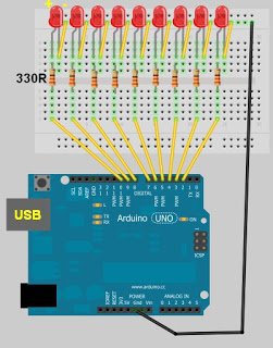
To connect ground to do this use a jumper wire to connect the ground pin on the arduino to the negative rail on the breadboard this allows all the LEDs to use the ground pin on the Arduino


Step2 


To insert the resistors into the breadboard space the resistors out with one leg connected to the negative rail on the breadboard


Step 3


insert the LEDs The longest pin is the positive (+) and the shortest pin is the negative(-). If it is wired the wrong way it will not operation


R = (5V – 3.3V) / 0.015

R = 113 ohm’s

We'll use the closest resistor value of 100 ohms.


source code :


int led = 13;
int led2 = 12;
int led3 = 11;

// the setup routine runs once when you press reset:
void setup() {
// initialize the digital pin as an output.
pinMode(led, OUTPUT);
pinMode(led2, OUTPUT);
pinMode(led3, OUTPUT);
}
// the loop routine runs over and over again forever:
void loop() {
digitalWrite(led, HIGH); // turn the LED on (HIGH is the voltage level)
delay(100); // wait for a second
digitalWrite(led, LOW); // turn the LED off by making the voltage LOW
delay(100);
{digitalWrite(led2, HIGH);
delay(100);
digitalWrite(led2, LOW);
delay(100);}
{digitalWrite(led3, HIGH);
delay(100);
digitalWrite(led3, LOW);
delay(100);}// wait for a second
}

...........................................................................................................................................................


More projects:


Thursday 1 March 2018

Arduino Based CNC Machine Made from old DVD writer

HOW TO MAKE ARDUINO BASED CNC MACHINE using DVD writer AT HOME


Requiredments

1)Arduino Nano x1

2)Old DVD writer x2

3)Motor Driver (L293D) x2

4)16 pin IC socket x2

5) Veroboard doted x1 or you can make pcb

6)Male header & Female header

7)Female USB (For power the motors) or you can use 9v jack


8)Female Jumper wires

9) Nuts

10) BO motor clamp

11)1 Servo motor

12) Double sided tape


13)Pen

14)Acrylic sheet


Acrylic Sheet  Cutting and Drilling 


1pcs 12"x6" (Fore base)

2pcs 1.5"x7" (For X-Axis Stand)

1pcs 3"x3" (For Writing base)

3pcs 1.5"x3"(For Moving part of X-Axis & Y-Axis and also for pen holder)

8pcs .5"x,5" (For specer)

Marke for drilling then drill it


Extracted Old DVD Writer


Extracting  X-Axis and Y-Axis From Old DVD Writer and  Solding the  Wire With Stepper Motor


Attach 1.5"x 3" Sheet With Moving Part of X and Y-Axis by Using Glue Gun


following Circuit Board


Makeing a Pen Holder


Broken  DVD writer Shuter Mechanism

Attach Servo and connect with the Gear

Connect  sheet with moving part and also glue the pencil compass to hold the pen


Assemblying full parts


Board with connections following steps


Arduino Code for CNC Machine:


how To download and Use Arduino Uno Software under Windows

........................................................................................................................
#include <Servo.h>
#include <AFMotor.h>
#define LINE_BUFFER_LENGTH 512
char STEP = MICROSTEP ;
// Servo position for Up and Down
const int penZUp = 115;
const int penZDown = 83;
// Servo on PWM pin 10
const int penServoPin =10 ;
// Should be right for DVD steppers, but is not too important here
const int stepsPerRevolution = 48; 
// create servo object to control a servo
Servo penServo;  
// Initialize steppers for X- and Y-axis using this Arduino pins for the L293D H-bridge
AF_Stepper myStepperY(stepsPerRevolution,1);          
AF_Stepper myStepperX(stepsPerRevolution,2);  
/* Structures, global variables    */
struct point {
  float x;
  float y;
  float z;
};
// Current position of plothead
struct point actuatorPos;
//  Drawing settings, should be OK
float StepInc = 1;
int StepDelay = 0;
int LineDelay =0;
int penDelay = 50;
// Motor steps to go 1 millimeter.
// Use test sketch to go 100 steps. Measure the length of line.
// Calculate steps per mm. Enter here.
float StepsPerMillimeterX = 100.0;
float StepsPerMillimeterY = 100.0;
// Drawing robot limits, in mm
// OK to start with. Could go up to 50 mm if calibrated well.
float Xmin = 0;
float Xmax = 40;
float Ymin = 0;
float Ymax = 40;
float Zmin = 0;
float Zmax = 1;
float Xpos = Xmin;
float Ypos = Ymin;
float Zpos = Zmax; 
// Set to true to get debug output.
boolean verbose = false;
//  Needs to interpret
//  G1 for moving
//  G4 P300 (wait 150ms)
//  M300 S30 (pen down)
//  M300 S50 (pen up)
//  Discard anything with a (
//  Discard any other command!
/**********************
 * void setup() - Initialisations
 ***********************/
void setup() {
  //  Setup

  Serial.begin( 9600 );

  penServo.attach(penServoPin);
  penServo.write(penZUp);
  delay(100);
  // Decrease if necessary
  myStepperX.setSpeed(600);
  myStepperY.setSpeed(600);

  //  Set & move to initial default position
  // TBD
  //  Notifications!!!
  Serial.println("Mini CNC Plotter alive and kicking!");
  Serial.print("X range is from ");
  Serial.print(Xmin);
  Serial.print(" to ");
  Serial.print(Xmax);
  Serial.println(" mm.");
  Serial.print("Y range is from ");
  Serial.print(Ymin);
  Serial.print(" to ");
  Serial.print(Ymax);
  Serial.println(" mm.");
}
/**********************
 * void loop() - Main loop
 ***********************/
void loop()
{

  delay(100);
  char line[ LINE_BUFFER_LENGTH ];
  char c;
  int lineIndex;
  bool lineIsComment, lineSemiColon;
  lineIndex = 0;
  lineSemiColon = false;
  lineIsComment = false;
  while (1) {
    // Serial reception - Mostly from Grbl, added semicolon support
    while ( Serial.available()>0 ) {
      c = Serial.read();
      if (( c == '\n') || (c == '\r') ) {             // End of line reached
        if ( lineIndex > 0 ) {                        // Line is complete. Then execute!
          line[ lineIndex ] = '\0';                   // Terminate string
          if (verbose) {
            Serial.print( "Received : ");
            Serial.println( line );
          }
          processIncomingLine( line, lineIndex );
          lineIndex = 0;
        }
        else {
          // Empty or comment line. Skip block.
        }
        lineIsComment = false;
        lineSemiColon = false;
        Serial.println("ok");  
      }
      else {
        if ( (lineIsComment) || (lineSemiColon) ) {   // Throw away all comment characters
          if ( c == ')' )  lineIsComment = false;     // End of comment. Resume line.
        }
        else {
          if ( c <= ' ' ) {                           // Throw away whitepace and control characters
          }
          else if ( c == '/' ) {                    // Block delete not supported. Ignore character.
          }
          else if ( c == '(' ) {                    // Enable comments flag and ignore all characters until ')' or EOL.
            lineIsComment = true;
          }
          else if ( c == ';' ) {
            lineSemiColon = true;
          }
          else if ( lineIndex >= LINE_BUFFER_LENGTH-1 ) {
            Serial.println( "ERROR - lineBuffer overflow" );
            lineIsComment = false;
            lineSemiColon = false;
          }
          else if ( c >= 'a' && c <= 'z' ) {        // Upcase lowercase
            line[ lineIndex++ ] = c-'a'+'A';
          }
          else {
            line[ lineIndex++ ] = c;
          }
        }
      }
    }
  }
}
void processIncomingLine( char* line, int charNB ) {
  int currentIndex = 0;
  char buffer[ 64 ];                                 // Hope that 64 is enough for 1 parameter
  struct point newPos;
  newPos.x = 0.0;
  newPos.y = 0.0;
  //  Needs to interpret
  //  G1 for moving
  //  G4 P300 (wait 150ms)
  //  G1 X60 Y30
  //  G1 X30 Y50
  //  M300 S30 (pen down)
  //  M300 S50 (pen up)
  //  Discard anything with a (
  //  Discard any other command!
  while( currentIndex < charNB ) {
    switch ( line[ currentIndex++ ] ) {              // Select command, if any
    case 'U':
      penUp();
      break;
    case 'D':
      penDown();
      break;
    case 'G':
      buffer[0] = line[ currentIndex++ ];          // /!\ Dirty - Only works with 2 digit commands
      //      buffer[1] = line[ currentIndex++ ];
      //      buffer[2] = '\0';
      buffer[1] = '\0';
      switch ( atoi( buffer ) ){                   // Select G command
      case 0:                                   // G00 & G01 - Movement or fast movement. Same here
      case 1:
        // /!\ Dirty - Suppose that X is before Y
        char* indexX = strchr( line+currentIndex, 'X' );  // Get X/Y position in the string (if any)
        char* indexY = strchr( line+currentIndex, 'Y' );
        if ( indexY <= 0 ) {
          newPos.x = atof( indexX + 1);
          newPos.y = actuatorPos.y;
        }
        else if ( indexX <= 0 ) {
          newPos.y = atof( indexY + 1);
          newPos.x = actuatorPos.x;
        }
        else {
          newPos.y = atof( indexY + 1);
          indexY = '\0';
          newPos.x = atof( indexX + 1);
        }
        drawLine(newPos.x, newPos.y );
        //        Serial.println("ok");
        actuatorPos.x = newPos.x;
        actuatorPos.y = newPos.y;
        break;
      }
      break;
    case 'M':
      buffer[0] = line[ currentIndex++ ];        // /!\ Dirty - Only works with 3 digit commands
      buffer[1] = line[ currentIndex++ ];
      buffer[2] = line[ currentIndex++ ];
      buffer[3] = '\0';
      switch ( atoi( buffer ) ){
      case 300:
        {
          char* indexS = strchr( line+currentIndex, 'S' );
          float Spos = atof( indexS + 1);
          //         Serial.println("ok");
          if (Spos == 30) {
            penDown();
          }
          if (Spos == 50) {
            penUp();
          }
          break;
        }
      case 114:                                // M114 - Repport position
        Serial.print( "Absolute position : X = " );
        Serial.print( actuatorPos.x );
        Serial.print( "  -  Y = " );
        Serial.println( actuatorPos.y );
        break;
      default:
        Serial.print( "Command not recognized : M");
        Serial.println( buffer );
      }
    }
  }
}
/*********************************
 * Draw a line from (x0;y0) to (x1;y1).
 * int (x1;y1) : Starting coordinates
 * int (x2;y2) : Ending coordinates
 **********************************/
void drawLine(float x1, float y1) {
  if (verbose)
  {
    Serial.print("fx1, fy1: ");
    Serial.print(x1);
    Serial.print(",");
    Serial.print(y1);
    Serial.println("");
  }  
  //  Bring instructions within limits
  if (x1 >= Xmax) {
    x1 = Xmax;
  }
  if (x1 <= Xmin) {
    x1 = Xmin;
  }
  if (y1 >= Ymax) {
    y1 = Ymax;
  }
  if (y1 <= Ymin) {
    y1 = Ymin;
  }
  if (verbose)
  {
    Serial.print("Xpos, Ypos: ");
    Serial.print(Xpos);
    Serial.print(",");
    Serial.print(Ypos);
    Serial.println("");
  }
  if (verbose)
  {
    Serial.print("x1, y1: ");
    Serial.print(x1);
    Serial.print(",");
    Serial.print(y1);
    Serial.println("");
  }
  //  Convert coordinates to steps
  x1 = (int)(x1*StepsPerMillimeterX);
  y1 = (int)(y1*StepsPerMillimeterY);
  float x0 = Xpos;
  float y0 = Ypos;
  //  Let's find out the change for the coordinates
  long dx = abs(x1-x0);
  long dy = abs(y1-y0);
  int sx = x0<x1 ? StepInc : -StepInc;
  int sy = y0<y1 ? StepInc : -StepInc;
  long i;
  long over = 0;
  if (dx > dy) {
    for (i=0; i<dx; ++i) {
      myStepperX.onestep(sx,STEP);
      over+=dy;
      if (over>=dx) {
        over-=dx;
        myStepperY.onestep(sy,STEP);
      }
    delay(StepDelay);
    }
  }
  else {
    for (i=0; i<dy; ++i) {
      myStepperY.onestep(sy,STEP);
      over+=dx;
      if (over>=dy) {
        over-=dy;
        myStepperX.onestep(sx,STEP);
      }
      delay(StepDelay);
    }  
  }
  if (verbose)
  {
    Serial.print("dx, dy:");
    Serial.print(dx);
    Serial.print(",");
    Serial.print(dy);
    Serial.println("");
  }
  if (verbose)
  {
    Serial.print("Going to (");
    Serial.print(x0);
    Serial.print(",");
    Serial.print(y0);
    Serial.println(")");
  }
  //  Delay before any next lines are submitted
  delay(LineDelay);
  //  Update the positions
  Xpos = x1;
  Ypos = y1;
}

//  Raises pen
void penUp() {
  penServo.write(penZUp);
  delay(penDelay);
  Zpos=Zmax;
  digitalWrite(15, LOW);
    digitalWrite(16, HIGH);
  if (verbose) {
    Serial.println("Pen up!");
 
  }
}
//  Lowers pen
void penDown() {
  penServo.write(penZDown);
  delay(penDelay);
  Zpos=Zmin;
  digitalWrite(15, HIGH);
    digitalWrite(16, LOW);
  if (verbose) {
    Serial.println("Pen down.");
  }
}


.............................................................................................................................