Saturday, 3 March 2018

Arduino Voice Controlled Robot


Arduino and Android Voice control Robot 

In this  touturial about How to make a voice control robot. voice controlled robot and is controlled via Bluetooth HC-05 through a smartphone applicaton. In this application is developed in such a way that it converts the voice command to text and transfer the text to the connected Bluetooth device


Required Components:
  1. Arduino Uno 
  2. Bluetooth Module
  3. L293D Motor Driver
  4. 2x Gear Motor
  5. 2x Wheel
  6. 1x Chasis
  7. A breadboard 
  8. Connecting wires


Circuit  Diagram :


Bluetooth module ----------- Arduino:
Vcc ----------- +5v
GND ----------- GND
Tx --------------- pin 10
Rx --------------- pin 11


Voice Control Bot App:

Here in this link is the app developed using MIT app inventor:


Click here to download Android app

This is a simplified version of any other voice control robot, No complex coding easy to understand coding with easy algorithm.

The app is developed in such a way that it convert the voice command to text and transfer the text to the connected Bluetooth device


Source Code:


Arduino Program for voice control robot.
_________________________________________________________________________________

#include <SoftwareSerial.h>

SoftwareSerial BT(10, 11); //TX, RX respetively
String readvoice;

void setup() {
 BT.begin(9600);
 Serial.begin(9600);
  pinMode(3, OUTPUT);
  pinMode(4, OUTPUT);
  pinMode(5, OUTPUT);
  pinMode(6, OUTPUT);

}
//-----------------------------------------------------------------------// 
void loop() {
  while (BT.available()){  //Check if there is an available byte to read
  delay(10); //Delay added to make thing stable
  char c = BT.read(); //Conduct a serial read
  readvoice += c; //build the string- "forward", "reverse", "left" and "right"
  } 
  if (readvoice.length() > 0) {
    Serial.println(readvoice);

  if(readvoice == "forward")
  {
    digitalWrite(3, HIGH);
    digitalWrite (4, HIGH);
    digitalWrite(5,LOW);
    digitalWrite(6,LOW);
    delay(100);
  }

  else if(readvoice == "reverse")
  {
    digitalWrite(3, LOW);
    digitalWrite(4, LOW);
    digitalWrite(5, HIGH);
    digitalWrite(6,HIGH);
    delay(100);
  }

  else if (readvoice == "right")
  {
    digitalWrite (3,HIGH);
    digitalWrite (4,LOW);
    digitalWrite (5,LOW);
    digitalWrite (6,LOW);
    delay (100);
  
  }

 else if ( readvoice == "left")
 {
   digitalWrite (3, LOW);
   digitalWrite (4, HIGH);
   digitalWrite (5, LOW);
   digitalWrite (6, LOW);
   delay (100);
 }

 else if (readvoice == "stop")
 {
   digitalWrite (3, LOW);
   digitalWrite (4, LOW);
   digitalWrite (5, LOW);
   digitalWrite (6, LOW);
   delay (100);
 }
readvoice="";}} //Reset the variable

_________________________________________________________________________________


Talk with Arduino Board using with Voice Recognition Module


 SERIAL VOICE RECOGNITION MODULE

we are learn how to talk with the Arduino Board. For this we will use the Voice Control Module. So, we can use this module to control motors, lights and robots.


Required Components :-
  1. Arduino uno
  2. Breadboard (or breadboard shield)
  3. Voice Recognition Module (serial)
  4. Microphone
  5. RGB LED
  6. 3x 220 Ohm resistors


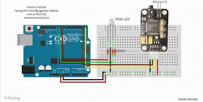
Connection between Arduino* and module for recording procedure:


Module Vcc to Arduino 5V
Module GND to Arduino GND
Module RX to Arduino RX
Module TX to Arduino TX


*You must remove ATmega328p from board or program it with blink example. If you want you can also use one usb to serial board to complete this procedure.

Available commands:

Delete Group 1 - send hex AA 01
Delete Group 2 - send hex AA 02
Delete Group 3 - send hex AA 03
Delete All Groups - send hex AA 04
Record Group 1 - send hex AA 11
Record Group 2 - send hex AA 12
Record Group 3 - send hex AA 13
Import Group 1 - send hex AA 21
Import Group 2 - send hex AA 22
Import Group 3 - send hex AA 23
Query the recorded group - send hex AA 24


Circuit  Diagram :


connections are pretty easy, see the above image with the breadboard circuit schematic


Source code :


how To download and Use Arduino Uno Software under Windows


int redPin = 9; // R petal on RGB LED module connected to digital pin 11
int greenPin = 10; // G petal on RGB LED module connected to digital pin 9
int bluePin = 11; // B petal on RGB LED module connected to digital pin 10
byte com = 0; //reply from voice recognition
void setup()
{
Serial.begin(9600);
pinMode(redPin, OUTPUT); // sets the redPin to be an output
pinMode(greenPin, OUTPUT); // sets the greenPin to be an output
pinMode(bluePin, OUTPUT); // sets the bluePin to be an output
delay(2000);
Serial.write(0xAA);
Serial.write(0x37);
delay(1000);
Serial.write(0xAA);
Serial.write(0x21);
color(255,255,255); // turn RGB LED on -- white
delay(5000);
}

void loop() // run over and over again
{
while(Serial.available())
{
com = Serial.read();
switch(com)
{
case 0x11:
color(255,255,255); // turn RGB LED on -- white
break;
case 0x12:
color(255, 0, 0); // turn the RGB LED red
break;
case 0x13:
color(0,255, 0); // turn the RGB LED green
break;
case 0x14:
color(0, 0, 255); // turn the RGB LED blue
break;
case 0x15:
color(0,0,0); // turn the RGB LED off
break;
}
}
}

void color (unsigned char red, unsigned char green, unsigned char blue) // the color generating function
{
analogWrite(redPin, red*102/255);
analogWrite(bluePin, blue*173/255);
analogWrite(greenPin, green*173/255);

}

.....................................................................................................................................................


More projects:


Friday, 2 March 2018

Fingerprint sensor scanner with Arduino

Fingerprint sensor scanner with Arduino
If you want to add biometric security features to your Arduino projects, an easy way to do so, is to add a fingerprint sensor module to it. In this video we demonstrate how easy to use a fingerprint sensor with an Arduino Nano and a small display.


Required Components :-
  1. Arduino Uno
  2. 16x2 LCD
  3. fingerprint sensor
  4. 10k potentionmeter
  5. 220ohms resistor = 3pcs
  6. red LED
  7. green LED
  8. jumper wires
  9. breadboard

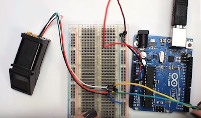
Circuit  Diagram :


Load the Fingerprint Sketch With LCD Sketch


Next step


Source Code:

how To download and Use Arduino Uno Software under Windows


/********************** ARDUINO FINGERPRINT SCANNER with 16x2 LCD monitor***************/
#include
#include
#include
#include
int getFingerprintIDez();
// pin #2 is IN from sensor (GREEN wire)
// pin #3 is OUT from arduino (WHITE wire)
SoftwareSerial mySerial(2, 3);
LiquidCrystal lcd(9, 8, 7, 6, 5, 4); // initialize the library with the numbers of the interface pins
Adafruit_Fingerprint finger = Adafruit_Fingerprint(&mySerial);
void setup()
{ Serial.begin(9600); // initialize the serial communications:
lcd.begin(16,2); lcd.setCursor(0,0); lcd.print("Scan your finger");
pinMode(13,OUTPUT);
pinMode(12,OUTPUT);
pinMode(11, OUTPUT);
pinMode(A0, INPUT);
finger.begin(57600); // set the data rate for the sensor serial port }
void loop() // run over and over again
{
getFingerprintID();
delay(100);
digitalWrite (13,HIGH);
}
uint8_t getFingerprintID()
{ uint8_t p = finger.getImage();
switch (p)
{
case FINGERPRINT_OK:
lcd.clear();
lcd.print(" Image taken... ");
delay(1000);
break;
case FINGERPRINT_NOFINGER:
return p;
case FINGERPRINT_PACKETRECIEVEERR:
return p;
case FINGERPRINT_IMAGEFAIL:
return p;
default:
return p; }
// OK success!
p = finger.image2Tz();
switch (p) {
case FINGERPRINT_OK:
break;
case FINGERPRINT_IMAGEMESS:
return p;
case FINGERPRINT_PACKETRECIEVEERR:
return p;
case FINGERPRINT_FEATUREFAIL:
return p;
case FINGERPRINT_INVALIDIMAGE:
return p;
default:
return p; }
// OK converted!
p = finger.fingerFastSearch();
if (p == FINGERPRINT_OK)
{
lcd.clear();
lcd.print(" Found match! ");
digitalWrite(11, HIGH);
delay(1000);
digitalWrite(11,LOW); // turn on green LED to indicate match
}
else if(p == FINGERPRINT_NOTFOUND)
{
lcd.clear();
lcd.setCursor(0,0);
lcd.print(" Did not match! ");
delay(1000);
lcd.clear();
lcd.setCursor(0,0);
lcd.print(" scan finger! ");
return p;
}
else
{ return p; }
// IF FOUND A MATCH............
lcd.clear();
lcd.setCursor(0,0);
lcd.print("Found ID #");
lcd.print(finger.fingerID);
lcd.setCursor(0,1);
lcd.print("confidence ");
lcd.print(finger.confidence); }
// returns -1 if failed, otherwise returns ID #
int getFingerprintIDez() {
uint8_t p = finger.getImage();
if (p != FINGERPRINT_OK) return -1;
p = finger.image2Tz();
if (p != FINGERPRINT_OK) return -1;
p = finger.fingerFastSearch();
if (p != FINGERPRINT_OK) return -1;
// found a match!
digitalWrite(13, LOW);
delay(10);
digitalWrite(13, HIGH);
delay(10);
lcd.clear();
lcd.setCursor(0, 0);
lcd.print("Found ID # ");
lcd.print(finger.fingerID);
lcd.setCursor(0, 1);
lcd.print("confidence ");
lcd.print(finger.confidence);
return finger.fingerID;
}

........................................................................................................................................


More projects:


HOW TO MAKE A SIMPLE RADAR SYSTEM USING ARDUINO

SIMPLE RADAR SYSTEM WITH ARDUINO


In this Arduino Tutorial I will show you how you can make this cool looking radar using the Arduino Board and the Processing Development Environment. You can watch the following video or read the written tutorial below for more details.


Required Components :-

1.arduino microcontroller uno
2. servo motor
3. ultrasonic sensor
4.basic stucture to mount
5. jumper wires
6.arduino ide


Circuit  Diagram


made a cardboard stand for connecting the Ultrasonic sensor to the Servo motor. I folded it like it’s shown on the picture below, glued it and secured to the servo motor using a screw like this


Next step


Next step


Source Code:

// Includes the Servo library
#include <Servo.h>.
// Defines Tirg and Echo pins of the Ultrasonic Sensor
const int trigPin = 10;
const int echoPin = 11;
// Variables for the duration and the distance
long duration;
int distance;
Servo myServo; // Creates a servo object for controlling the servo motor
void setup() {
pinMode(trigPin, OUTPUT); // Sets the trigPin as an Output
pinMode(echoPin, INPUT); // Sets the echoPin as an Input
Serial.begin(9600);
myServo.attach(12); // Defines on which pin is the servo motor attached
}
void loop() {
// rotates the servo motor from 15 to 165 degrees
for(int i=15;i<=165;i++){
myServo.write(i);
delay(30);
distance = calculateDistance();// Calls a function for calculating the distance measured by the Ultrasonic sensor for each degree
Serial.print(i); // Sends the current degree into the Serial Port
Serial.print(","); // Sends addition character right next to the previous value needed later in the Processing IDE for indexing
Serial.print(distance); // Sends the distance value into the Serial Port
Serial.print("."); // Sends addition character right next to the previous value needed later in the Processing IDE for indexing
}
// Repeats the previous lines from 165 to 15 degrees
for(int i=165;i>15;i--){
myServo.write(i);
delay(30);
distance = calculateDistance();
Serial.print(i);
Serial.print(",");
Serial.print(distance);
Serial.print(".");
}
}
// Function for calculating the distance measured by the Ultrasonic sensor
int calculateDistance(){
digitalWrite(trigPin, LOW);
delayMicroseconds(2);
// Sets the trigPin on HIGH state for 10 micro seconds
digitalWrite(trigPin, HIGH);
delayMicroseconds(10);
digitalWrite(trigPin, LOW);
duration = pulseIn(echoPin, HIGH); // Reads the echoPin, returns the sound wave travel time in microseconds
distance= duration*0.034/2;
return distance;
}


For drawing the radar I made this function drawRadar() which consist of arc() and line() functions.
  1. void drawRadar() {
    pushMatrix();
    translate(960,1000); // moves the starting coordinats to new location
    noFill();
    strokeWeight(2);
    stroke(98,245,31);
    // draws the arc lines
    arc(0,0,1800,1800,PI,TWO_PI);
    arc(0,0,1400,1400,PI,TWO_PI);
    arc(0,0,1000,1000,PI,TWO_PI);
    arc(0,0,600,600,PI,TWO_PI);
    // draws the angle lines
    line(-960,0,960,0);
    line(0,0,-960*cos(radians(30)),-960*sin(radians(30)));
    line(0,0,-960*cos(radians(60)),-960*sin(radians(60)));
    line(0,0,-960*cos(radians(90)),-960*sin(radians(90)));
    line(0,0,-960*cos(radians(120)),-960*sin(radians(120)));
    line(0,0,-960*cos(radians(150)),-960*sin(radians(150)));
    line(-960*cos(radians(30)),0,960,0);
    popMatrix();
    }


How to Make a Line Following Robot without Microcontroller

Line Following Robot 


Learn - how to make a Line follower robot Without microcontroller DIY at home


It is a Robert that follows a line, either a black line on white surface. 

IR sensor will send a HIGH digital signal ("1"). similarly when the sensor is on a black surface IR rays will be emitted and will not be reflected back which will be absorbed by the black surface, in this state the IR sensor will send LOW digital signal ("0"). Thus with these digital values 1 and 0 we can easily identify the state of the sensors

Required Components :- 

1. Zero PCB Board 
2. IR Infrared Obstacle Avoidance Sensor Module 
3. 16 pin Ic base 
4. L293d ic base 
5. 60W Multi Purpose Hot Melt Glue Gun 
6. 7805 voltage regulator 
7. wood bit (10cm x 5cm x 2.5cm) 
8. BO Motor L Type - 60 RPM 
9. Red BO Motor Wheels 
10. plexiglass piece (10 x 5 cm) 
11. soldering wire 50gm 
12. Yellow Soldering Iron 
13. 10K ohm Variable Resistor 
14. Resistor(100ohm, 1k, 10K) etc.

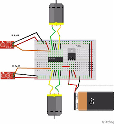
Diagram:


INPUT 1,2,3 and 4 of L293D will be thrown back to the OUTPUT 1,2,3 and 4 respectively. The INPUT 2 and 3 of L293D is connected to ground which is LOW("0") and the signal from the IR sensors are connected to INPUT 1 and 4. Hence the value of OUTPUT 2 and 3 will be constantly LOW("0") while the value of OUTPUT 1 and 4 will be HIGH("1") when the IR sensor is on the white surface and will be LOW("0") when the sensor is on black surface

Line Follower Robot using Arduino

IR sensor modules namely left sensor and right sensor. When both left and right sensor senses white then robot move forward


source code:


/*------ Arduino Line Follower Code----- */
/*-------definning Inputs------*/
#define LS 2      // left sensor
#define RS 3      // right sensor
/*-------definning Outputs------*/
#define LM1 4       // left motor
#define LM2 5       // left motor
#define RM1 6       // right motor
#define RM2 7       // right motor
void setup()
{
  pinMode(LS, INPUT);
  pinMode(RS, INPUT);
  pinMode(LM1, OUTPUT);
  pinMode(LM2, OUTPUT);
  pinMode(RM1, OUTPUT);
  pinMode(RM2, OUTPUT);
}

void loop()
{
  if(digitalRead(LS) && digitalRead(RS))     // Move Forward
  {
    digitalWrite(LM1, HIGH);
    digitalWrite(LM2, LOW);
    digitalWrite(RM1, HIGH);
    digitalWrite(RM2, LOW);
  }

  if(!(digitalRead(LS)) && digitalRead(RS))     // Turn right
  {
    digitalWrite(LM1, LOW);
    digitalWrite(LM2, LOW);
    digitalWrite(RM1, HIGH);
    digitalWrite(RM2, LOW);
  }

  if(digitalRead(LS) && !(digitalRead(RS)))     // turn left
  {
    digitalWrite(LM1, HIGH);
    digitalWrite(LM2, LOW);
    digitalWrite(RM1, LOW);
    digitalWrite(RM2, LOW);
  }

  if(!(digitalRead(LS)) && !(digitalRead(RS)))     // stop
  {
    digitalWrite(LM1, LOW);
    digitalWrite(LM2, LOW);
    digitalWrite(RM1, LOW);
    digitalWrite(RM2, LOW);
  }
}

............................................................................................................................................................

.


More projects:


How to How to Make a Self Balancing Robot

How to Make a Self Balancing Robot


Learn- How to make a self balancing robot by using Arduino.In this project i'm gonna show you the easiest way to do a simple, cheap and useless two wheels self-balancing robotI explain the materials and electronics used in the project, how and where to buy or create it and i'm gonna tell you my experience and tips.


Required of Components 


  1. Arduino Mega
  2. b6612Fng Dual Motor Driver
  3. Bluetooth Module BLE 4.0 MPU 6050
  4. Lipo Battery
  5. Motor and Wheels
  6. WHOLE KIT

Diagram:


The electronics we are going to use in the project are simply three, an arduino UNO you can use whatever arduino you have, doesn't matter if isn't arduino UNO a motor driver, in this case a L298, and finally an IMU.


Next Step


Source Code:

how To download and Use Arduino Uno Software under Windows


Self Balancing Robot Source Code  Download Link click here